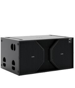
CLS-121S
Subwoofer unit in direct radiation configuration
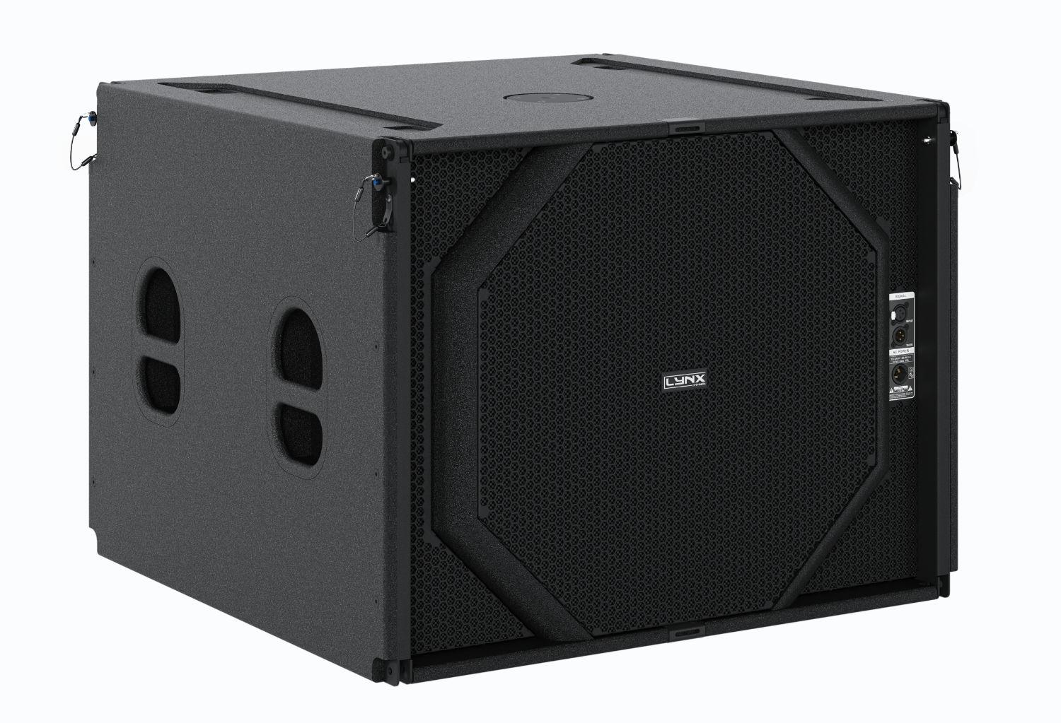
Compact & extremely powerful, self-powered (3000W Class-D with PFC), DSP integrated subwoofer unit in direct radiation configuration. 21” (4” voice coil) neodymium transducer.
Description
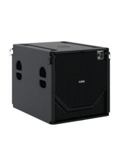
The CLS-121S is a high-output, extremely powerful sub-bass element designed to be used in unison with the coaxial CLS-212 line array module.
It uses one low distortion 21” (4” QUATTRO in/out copper voice coil) custom speaker with double silicon spider with optimized compliance, exclusive Malt Cross Technology cooling system for reduced power compression and aluminium demodulating ring for very low distortion.
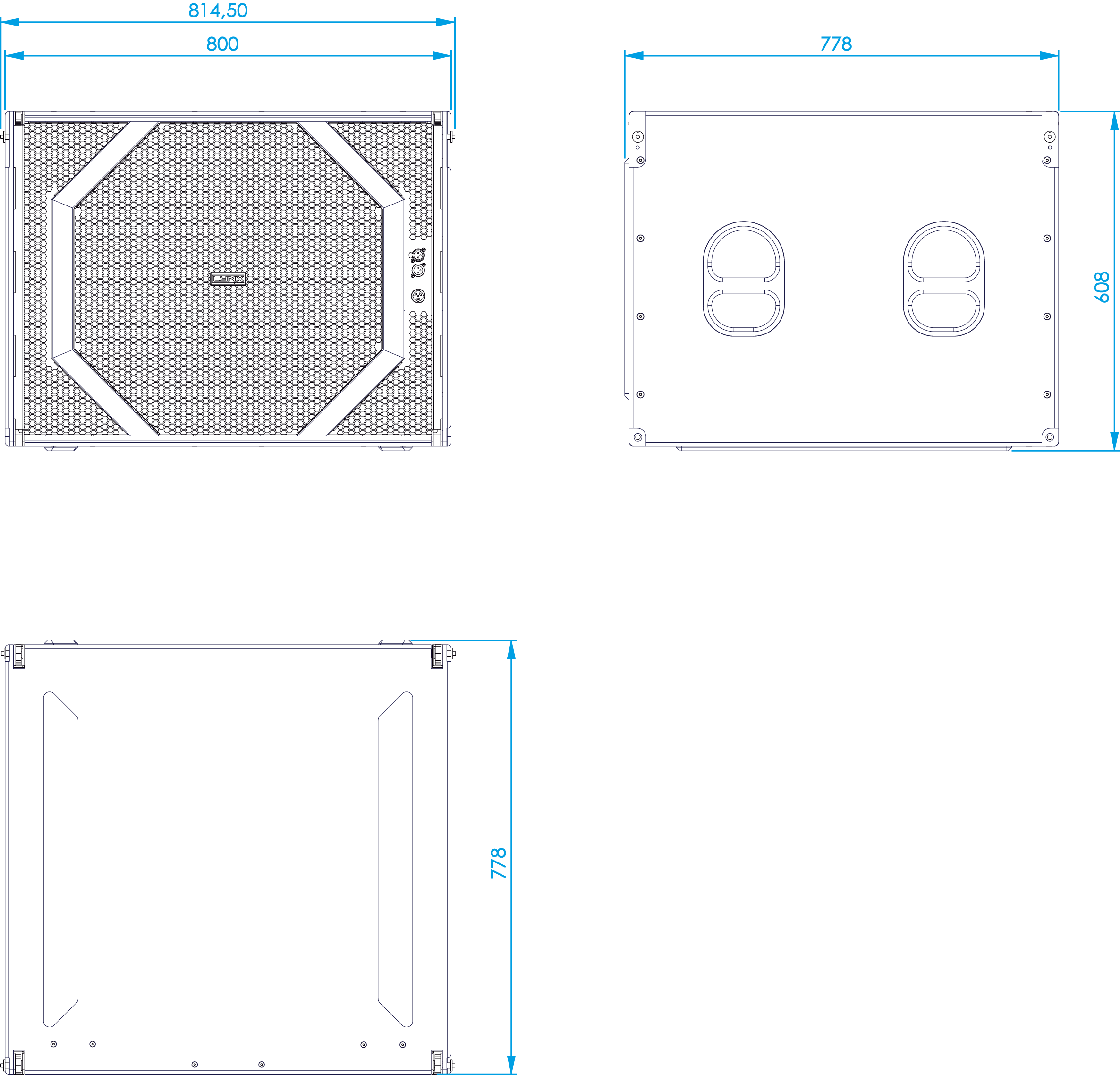
Designed to be used either as a standard sub bass unit or easily configurable in cardioid configuration thanks to integrated front & rear power connectors enable a discreet installation without any cables visible at the front of the cluster. The extra strong, especially designed internal wooden reinforcements reduce unwanted vibrations eliminating any noise, lowering distortion and delivering a clear sound. At the same time, the bass port is designed with a flare to eliminate any turbulence caused by sharp edges in the sound waves path.
The 3000W Class-D amplifier with PFC (Power Factor Correction) offers exceptional efficiency with maximum system performance whilst significantly lowering power consumption. With Thermal, short-circuit and overload protections the system module delivers an outstanding sonic performance. Coupled together with our new generation, 64 bit/96KHz processor the system electronics are yet further guaranteed not only the utmost protection but the best performance.
Designed in-house by Lynx Pro Audio engineers our DSP offers the most recent advances in digital processing such as FIR filters delivering a linear phase & frequency response. The latest 32 bit/96KHZ AD/DA converters make the system one of the most advanced & innovative line arrays on the market resulting in superior sound quality.
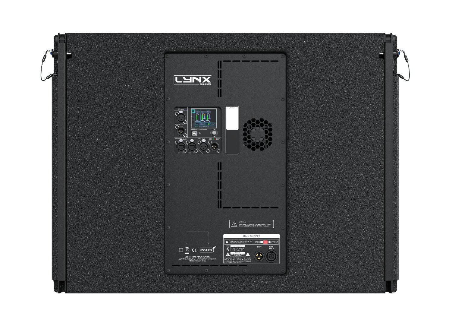
A 2.8” IPS user interface is located on the enclosure’s back panel and has multifunction joystick control enabling the user to control, select and/or adjust parameters such as cabinet presets, gain, delay and input EQ (see user manual). Two Ethernet ports enable the system to be controlled with the OCS platform for easier alignment, monitoring and processing of the array and together with the new Rainbow 3D prediction software delivers a complete system design tool.
The enclosure is made from premium grade birch plywood and finished with a polyurea coating for longer durability & weather protection. It also has a number of dedicated accessories available and the 4 point rigging system which includes 2 front automatically rising plates and 2 rear points which enable 10 CLS-121S cabinets to be flown in a single array or together with the CLS-212.
Key features
|
• Extraordinary high power output |
|
|
• Integrated Digital processor (64 bit / 96 KHz) |
|
|
• Front & rear audio and power connectors for cardioid applications |
|
|
• Ergonomic design in premium birch plywood & finished in polyurea |
|
|
• 2.8” IPS display with multifunction joystick control |
|
|
• Stackable and flyable standard and/or cardioid configuration |
|
|
Click here for DSP module configuration |
Perfectly suited for:
| → Touring and fixed installations | |
| → Sports stadiums | |
| → Houses of worship | |
| → Club installations | |
| → Concert halls and auditoriums | |
| → Low frequency complement for CLS-212 |
Technical Data
Components |
LF: 21” Neodymiun magnet transducer. 4” quattro in/out copper voice coil, Waterproof cone treated on both sides. Malt Cross Technology cooling system. Aluminium demodulating ring for very low distortion. 1600 W (AES) |
| Frequency Range | 30 Hz – 90 Hz (preset 90 Hz) |
Coverage |
Quasi omnidirectional |
| Max SPL/Peak | 131 dB / 137 dB |
Power amplifier |
3000W Class D with switching power supply & PFC |
| DSP | Internal Lynx Processor DSPB-FL. 96 KHz / 64 bit double-precision High performance 32 bit 96 KHz AD/DA converters 120dB |
Configuration |
Bass-reflex direct radiation enclosure |
| Control | User control interface with 2.8″ IPS and multifunction joystick controller |
Control connections |
USB (DSP programming)
|
| Input | BAL/ UNBAL XLR connectors analog input + loop AES/EBU digital input + loop |
Nominal Voltage |
100 – 240V AC @ 50-60 Hz |
| Operating Voltage | 85 – 264V AC |
AC Connectors |
16A Neutrik powerCON TRUE1 TOP with looping output |
| Finish | Polyurea coating, high grade resistant paint |
Material |
15 mm / 18 mm premium birch plywood |
| Dimensions | 608 x 800 x 778 mm (H x W x D) / with pins 814.5 mm (W) |
Weight |
64 Kg (141 lbs) |
 DSP configuration
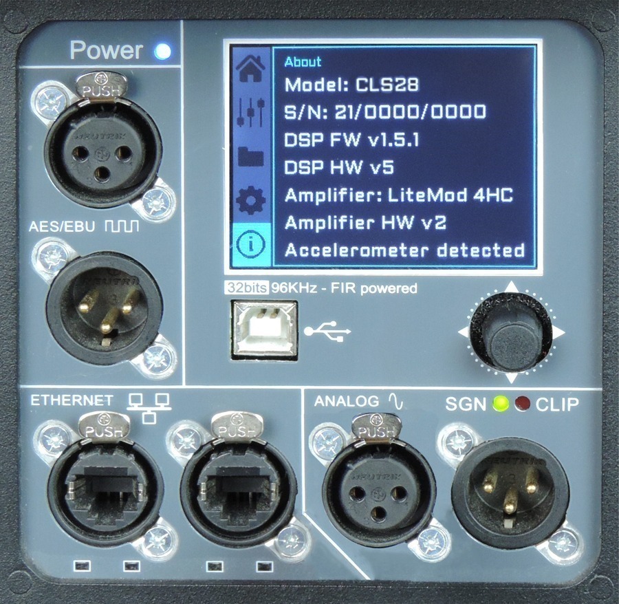
DSP module configuration panel
On the back pannel of the cabinet you will find the digital control area. From the compact joystick located below the screen you are able to configure the basic adjustment functions of the internal DSP.
Just move the joystick to select the icons on the left of the screen. You can enter into the following functions: Home, settings, folder, configuration and information. Please note that you must apply the desired configuration in each one cabinet and requires electrical power to work.
If changes are not made the display will automatically dim to avoid unnecessary light in situations where light is not wanted. To re-activate the light simply press the joystick.
The following screens are an example and may vary slightly for each cabinet.
Configuration panel:
Watch the following TUTORIAL to understand how it works:
DSP module configuration panel
On the back panel of the cabinet you will find the digital control area. From the compact joystick located below the screen you are able to configure the Basic adjustment functions of the internal DSP.
Just move the joystick to select the icons on the left of the screen. You can enter into the following functions: Home, settings, folder, configuration and information. Please note that you must apply the desired configuration in each one cabinet and requires electrical power to work.
If changes are not made the display will automatically dim to avoid unnecessary light in situations where light is not wanted. To re-activate the light simply press the joystick.
The following screens are an example and may vary slightly for each cabinet.
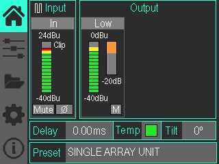
HOME
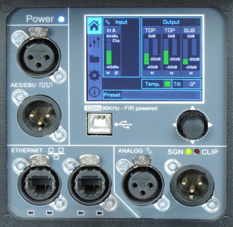
On the main screen you can see the cabinet’s input and output.
• Input: You can see a vumeter with the input level and a clip signal.
• Output: You have a vumeter with the output level (0 dBu is the amp’s maximum level) You can check the compressor and control the dynamic activity.
SETTINGS
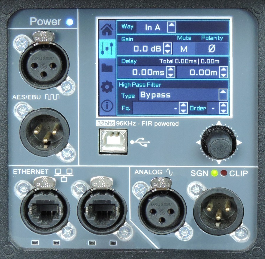
This panel allows you to change the gain, polarity, mute and the delay for the inputs.
You also have the possibility of putting a high pass, changing the type of filter, frequency and order.
FOLDER:
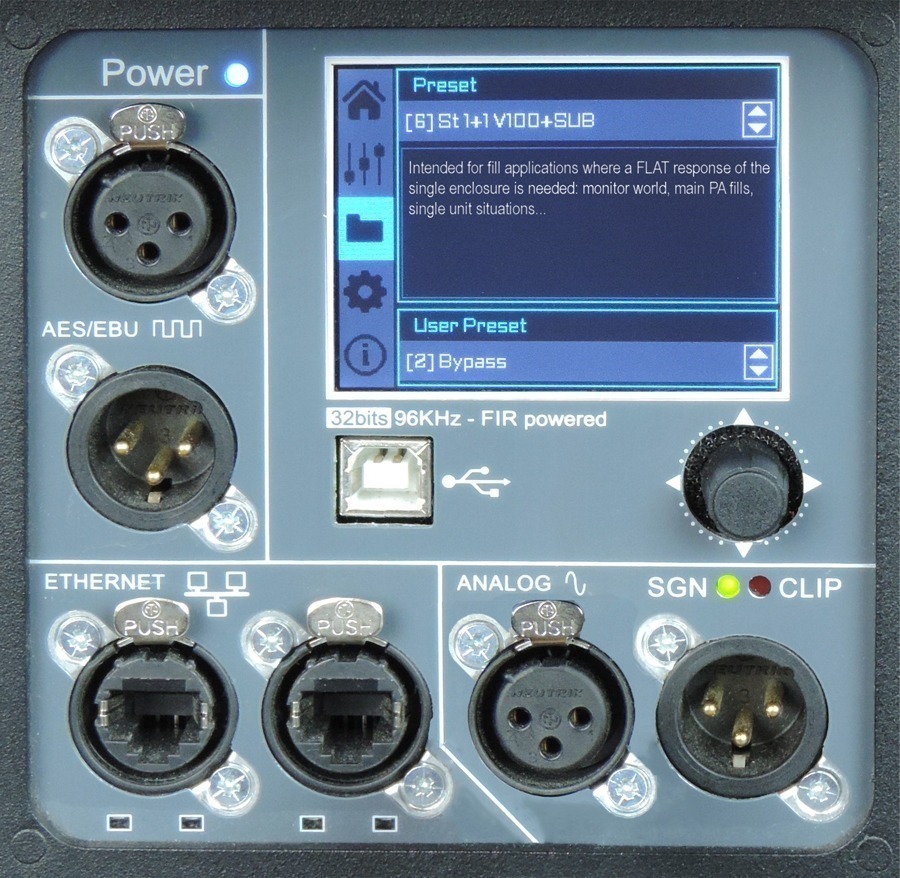
The folder screen shows you the name of the preset and its description.
Using the joystick you can change the preset.
CONFIGURATION:
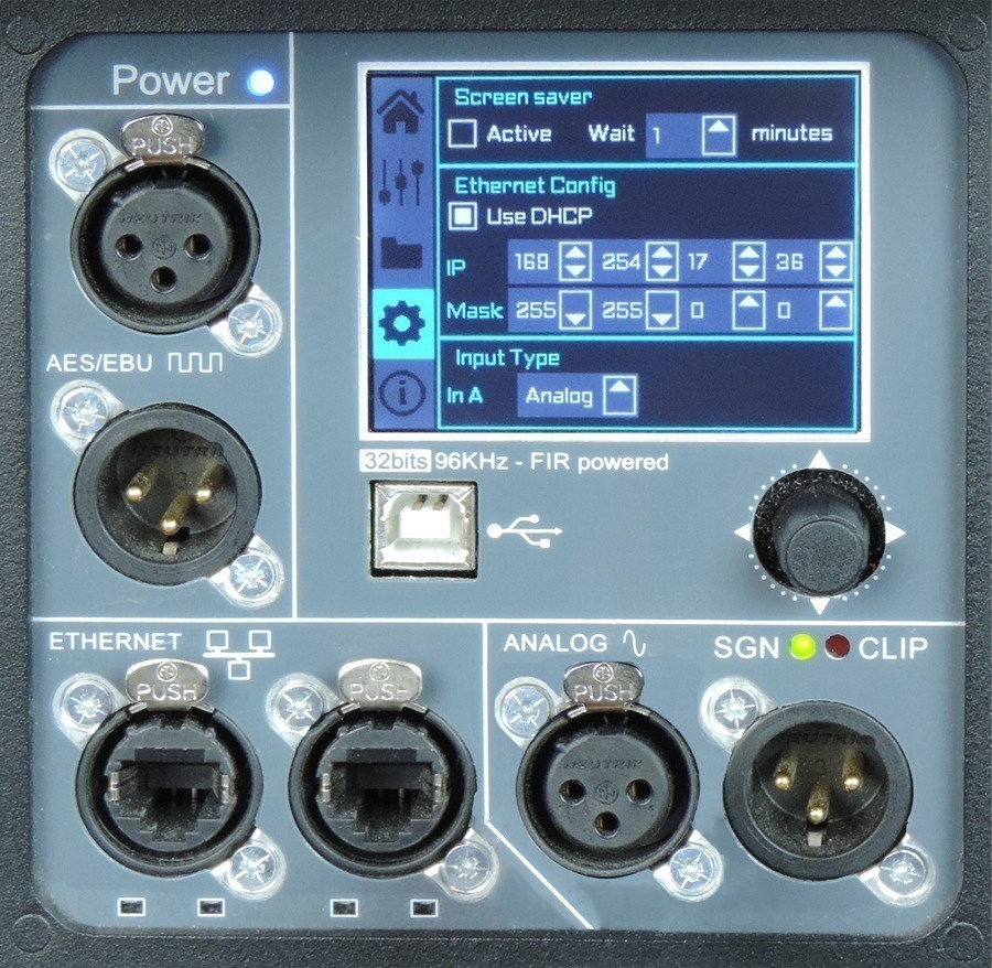
This screen is to configurate Ethernet. You can choose automatic or manual. You can also configure the screen saver.
And here you have the input selection. You can choose between analog or AES3 for channel 1 or channel 2.
INFORMATION:
The last screen shows you some general information regarding the cabinet’s components.
Here you can see the cabinet model, its serial number, DSP firmware and hardware versions, amp module model with hardware version, as well as the accelerometer status.
Watch the following TUTORIAL to understand how it works:
More features
Hardware for CLS-121S
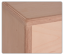 |
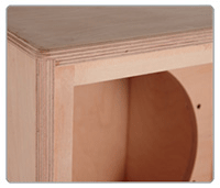
EnclosureThe CLS-121S cabinet is constructed from 11-ply and 13-ply premium birch plywood (15mm & 18mm thickness). The enclosure is finished with polyurea coating. |
 |
Internal designThe internal structure of the CLS-121S is heavily braced for greater longevity and all parts are assembled on metal inserts with metric screws. The amplification modules & DSP are housed in a separate chamber to the drivers avoiding excessive heat & vibration, thus delivering greater efficiency and reliability. |
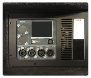 |
Rear panelThe powder coated steel front panel contains connections to power and signal for cardioid operation. It is located in the grill. |
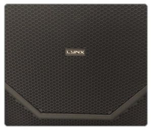 |
GrillThe CLS-121S has three heavy duty, powder coated front grille with a special acoustic rear fabric to protect the transducers against dust and dirt. |
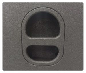 |
HandlesThe CLS-121S has four ergonomic handles with firm internal grip, two on each side of the enclosure, to facilitate transport, positioning and loading of the cabinets. |
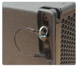 |
RiggingThe 4 point rigging system with 4 retractile levers which enable 10 CLS-121S cabinets to be flown in a single array or together with the CLS-212. Fixed 0º angle. Can be directly linked together with 6 CLS-212 through the connection system SC-CLS212/121S or more cabinets (up to 1000 kg) with the SV-CLS20 flying frame. |
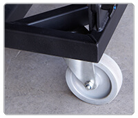 |
TransportThe CLS-121S has two transport options: a front squid cover with wheels (100mm) and a wood transport dolly. |
Accessories for CLS-121S
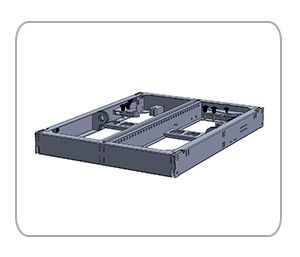 |
SV-CLS20 Flying frame for 16 CLS-212 or CLS-121S. |
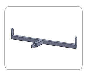 |
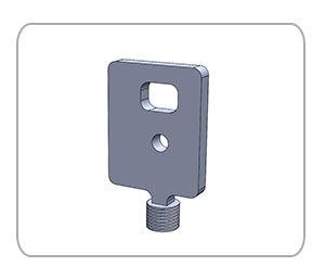
SC-CLS212/121S Connection system for CLS-28 together with CLS-118S |
 |
ST-SVCLS/M20 Kit to connect SV-CLS10 or SV-CLS20 flying frame and M20 plate |
 |
ST-CLSKIT 4 x ground stack stabilisers for SV-CLS10 |
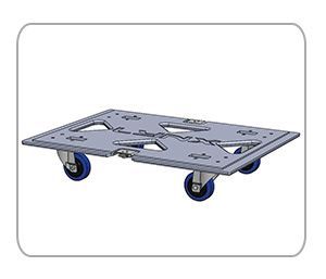 |
CA-CLS121S Removable front transport dolly
|
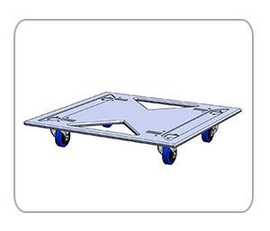 |
CA-CLS121S/2 Dolly for 2 CLS-121S |
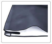 |
FD-CLS121S Nylon protection cover for CLS-121S with a CA-CLS121S FD-2CLS121S Nylon protection cover for 2 CLS-121S with a CA-CLS121S/2 |
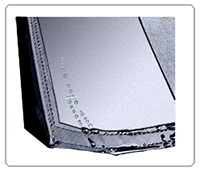 |
FD-CLSSUBNL Rain cover for CLS-118S / CLS-121S / CLS-218S |
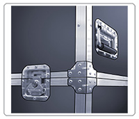 |
FC-SVCLS10 Flight case to transport 2 SV-CLS10, cables and accessories |
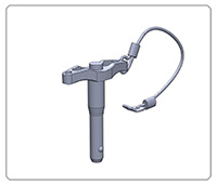 |
BALL-PSR0820 Ball pin with thread for CLS-212 cabinet and CLS-121S |
